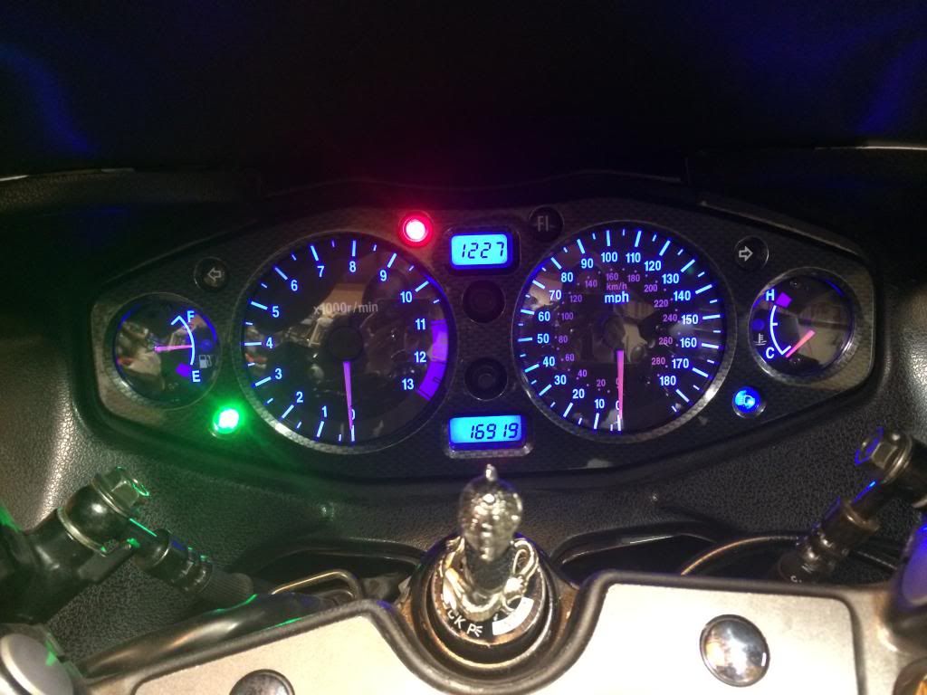
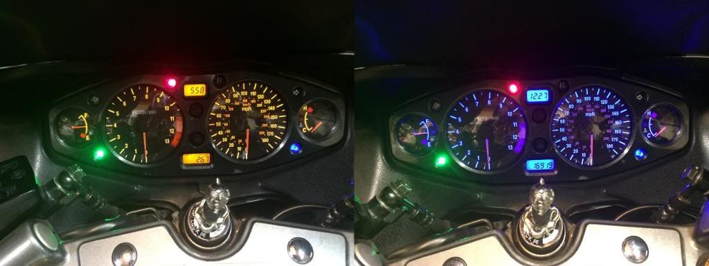
Hello everyone, this tutorial is meant for Generation 1 Hayabusa owners who would like to change the LED backlight to their gauges.
Items Required:
Small Phillips screwdriver
Regular Phillips screwdriver
Thin small flathead
Soldering Iron
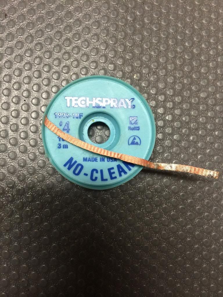
De-soldering wick
Solder
8MM socket wrench
Metric Allen Set
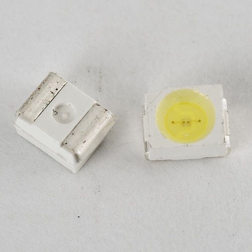
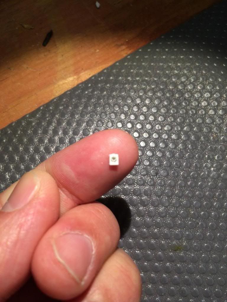
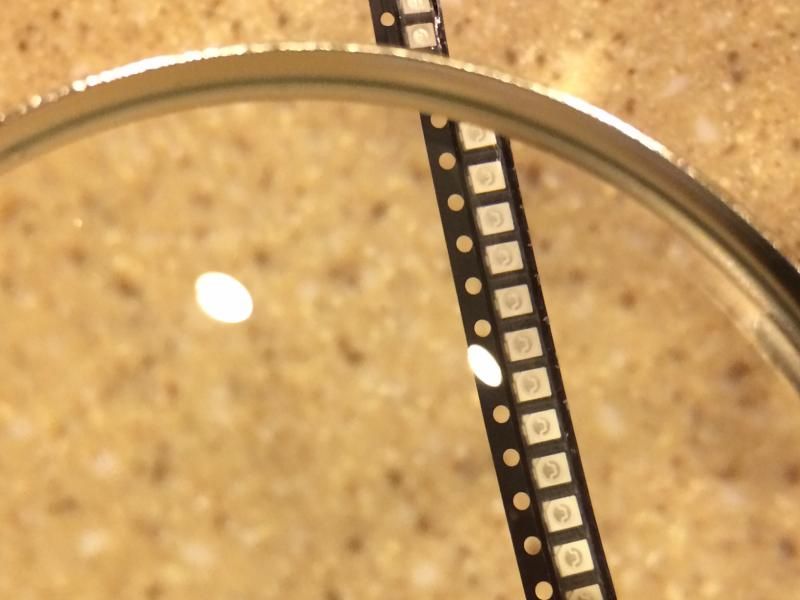
29 - PLCC-2 LED'S (I would suggest buying these on ebay in a 50 count package as you wil lmost likely damage some or lose some)
LED REQUIRED FOR FIRST GEN ONLY!!!!!! SECOND GEN REQUIRES A DIFFERENT STYLE LED!!!!
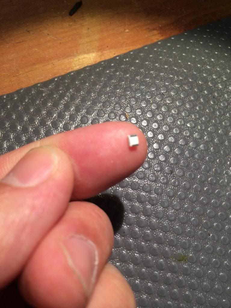
Foreward - This project is not super difficult but is also not for the faint of heart, you will be pulling your gauges apart and you do have the possibility to damage the board beyond repair. The LED's are incredibly small and some people may need to use a magnifying glass to be able to see properly.
Step 1:
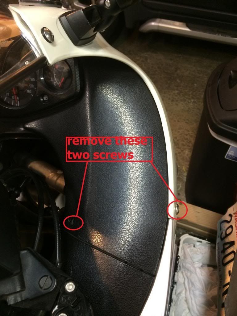
Remove Black side panels and windshield.
The black side panels are easily removed by two screws, and 1 push pin up top. Once those are removed, pull upwards and it should "unclip" from the body panels.
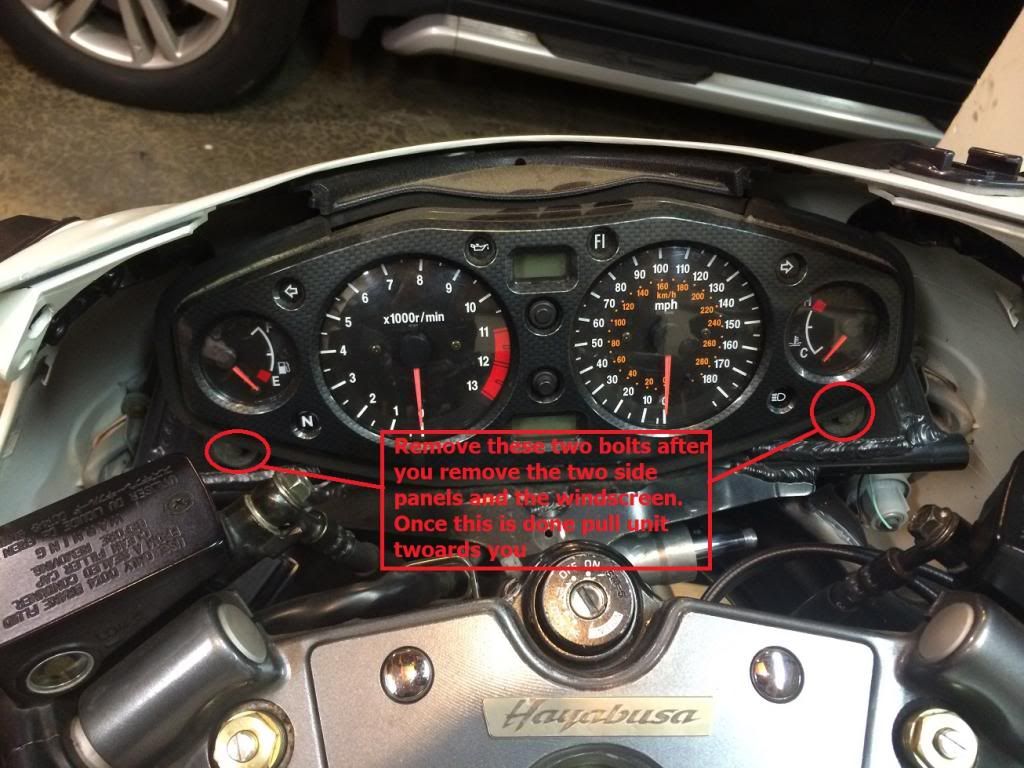
Step two:
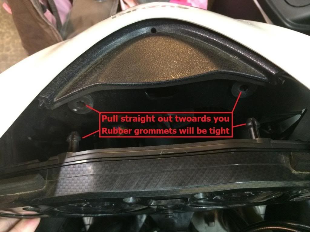
Once the side panels and windshield have been removed, remove the two 8mm bolts holding the gauge cluster onto the frame.
Once the bolts are removed, pull the cluster directly towards you as there are two rubber grommets at the top of the cluster holding it in. At this point it would be a good idea to place something soft in between the cluster and your triple tree to avoid damage to the cluster itself.
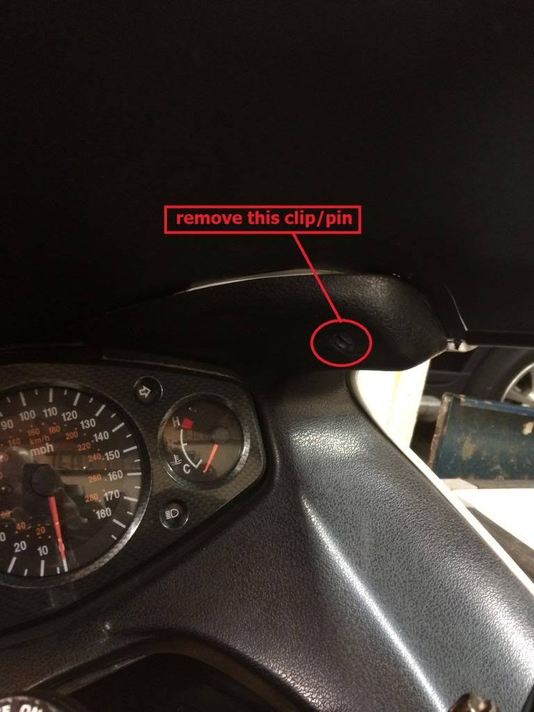
Once you have pulled this out, there is 1 clip covered by a rubber dust shield on the backside of the cluster that will need to be unclipped.
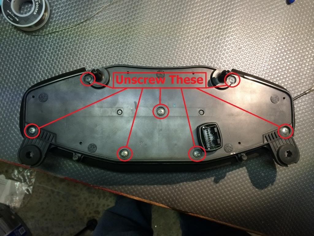
Step three:
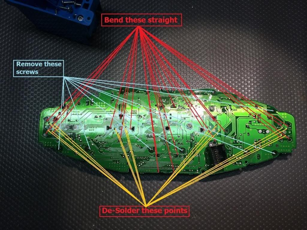
Once you have removed the gauge cluster turn the cluster over to the back side and remove the screws highlighted. Once the screws have been removed pull the back side of the cluster straight off. There may be a little resistance but it will only be from an old rubber gasket; try not to damage this gasket. Once the rear case is removed you should be free to remove the front, then seperate the board.
Step four:
Once you have separated everything the first thing you will want to do is remove the two LCD screens. These are easily removed by bending the 4 prongs straight and then just pull the unit out! This is not soldered in or held in place by any other means then the prongs. Make sure to remove and set to the side carefully so that they go back in the same way they came out. After you remove the screens we will start working on removing the gauge dial motors. You will need to bend those prongs up as well.
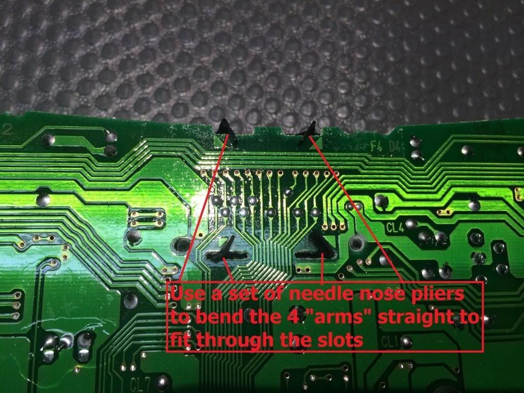
Step Five:
Now we are going to remove the dial motors, You NEED to do this, DO NOT PULL THE NEEDLES!!! If you pull the needles themselves they will not be calibrated properly and will need to be sent out.
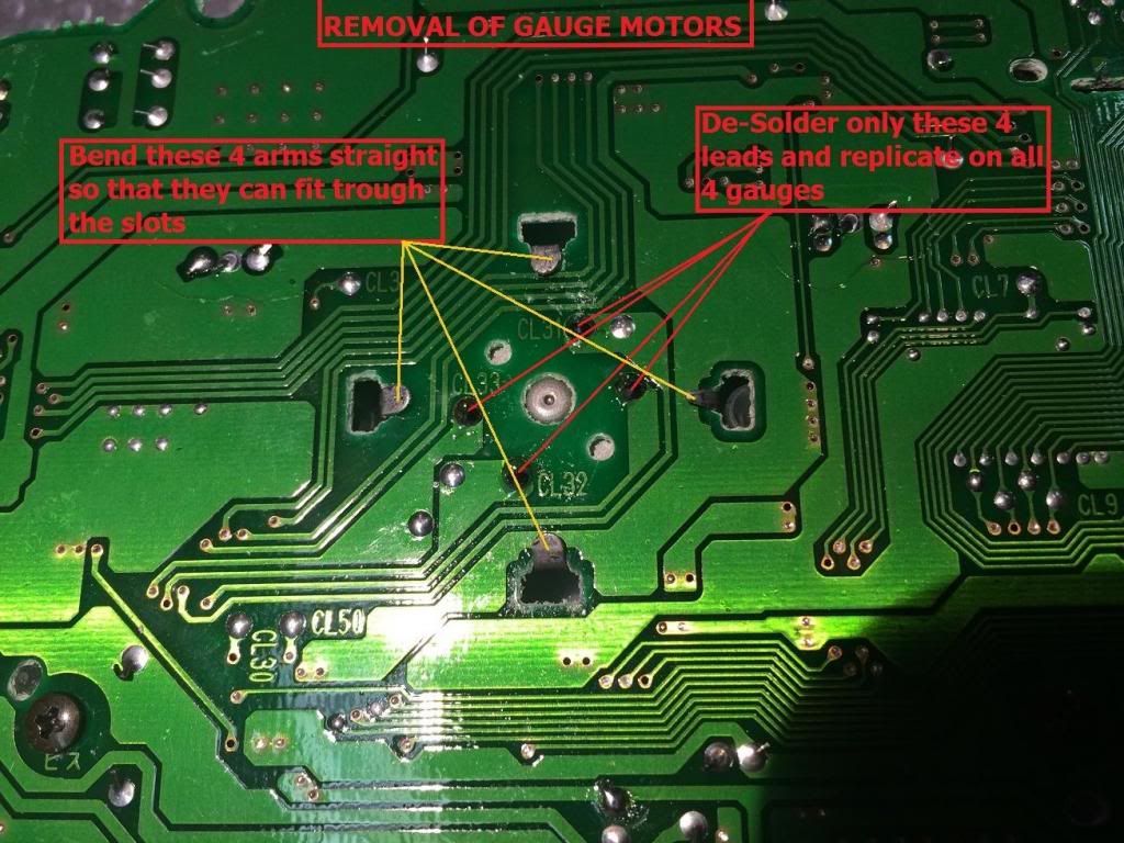
I suggest doing each dial independently, the first thing you will need to do it bend the 4 prongs up, then remove the 2 screws on the BACK of the cluster if you are working on the outside dials, or 3 screws if your working on the larger inside gauges (RPM AND SPEED). Once you have accomplished this, take your solder wick and soldering iron and touch the wick to the spot you would like to desolder then touch your iron to that to "Suck up" the solder. Do not do this for too long or you will damage to board or components. Once all 4 leads are desoldered then go to the front of the gauge and stick a small screwdriver in between the board and the dial motor and give it a little "Pop" if it is stuck on the board. Once the gauge is removed make sure to mark which lead is "up" so you can put it back in if it gets spun around. Repeat for all 4 gauges.
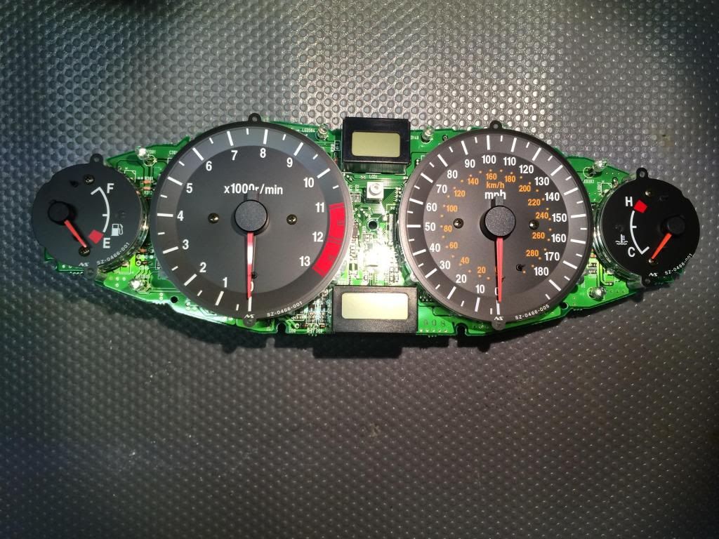
Step Seven:
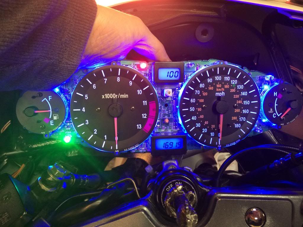
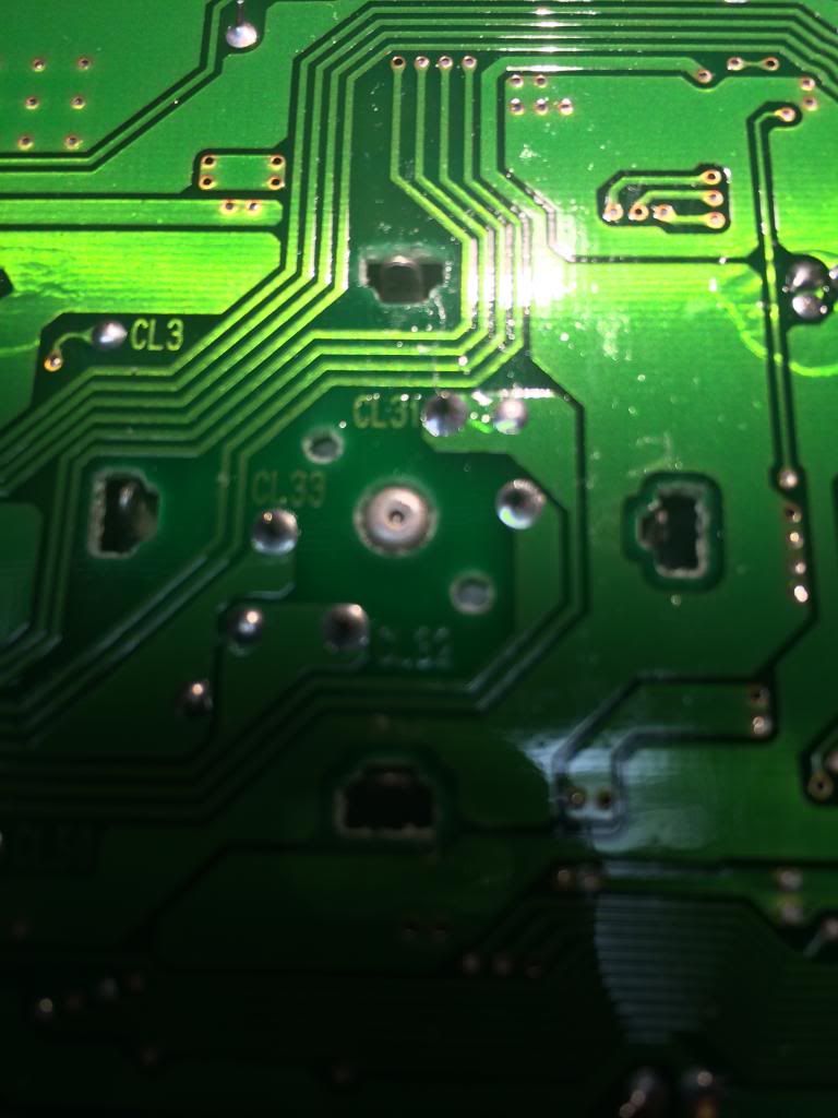
Once all the components are removed you will be able to see all the locations of where the LEDS need to be removed. To showcase this im going to show the completed blue board for easier view.
To remove the LEDS take a very small jewelers flathead screwdriver and place it on one side of the LED, touch that side of the led with your soldering iron and lift that side of the led up when the solder has melted. Wait a few seconds for the board to cool, then take a pair of tweezers and grab the led and melt the solder on the other side to release the LED. You do not have to worry about orientation of the old LED because the board shows on every location which way you put "The notch" of the LED. Remove all of the LEDS at once so that you get into a rhythm. If you try to complete each one it will take forever.
Once all the LEDS are removed, i suggest going over all the leads on the board with your solder wick to clean up your work area. after that, grab a led, match it up to the orientation shown on the board itself making sure you put "The notch" in the right direction, then resolder each side of the LED.
*****KEEP IN MIND THESE LEDS ARE VERY VERY SENSITIVE TO HEAT DO NOT TAKE TO LONG SOLDERING!!!!!!******

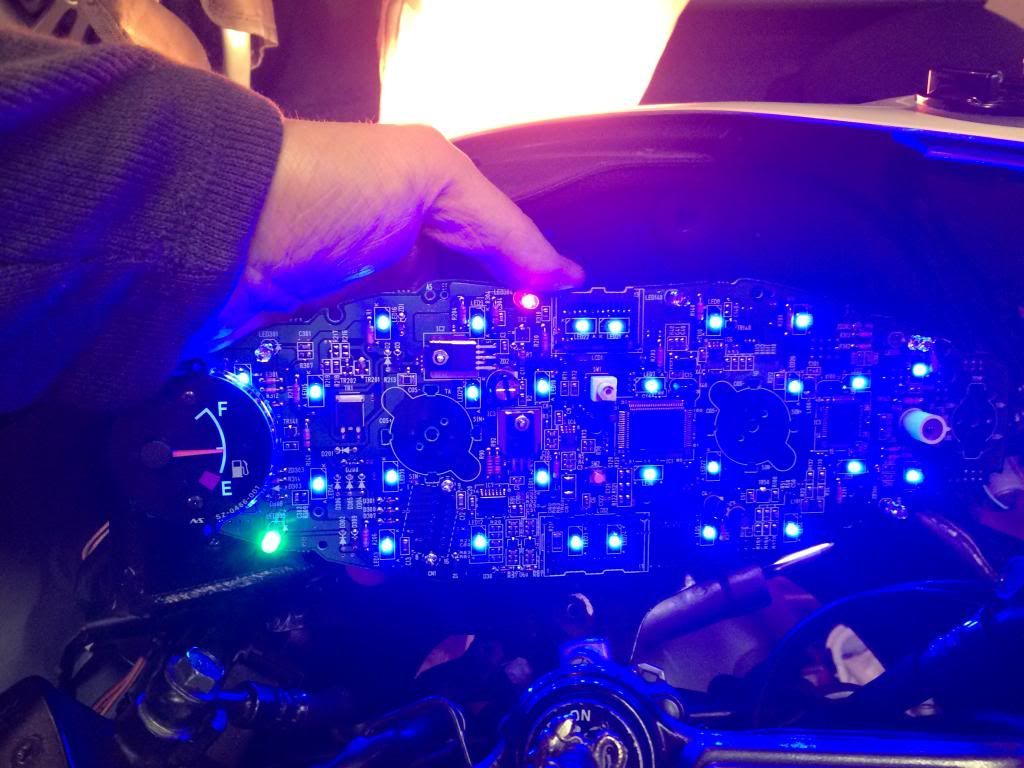
Step 8:
Once you have all the LEDS in, you CAN test the board without the gauges in without damage. Go back to your bike MAKE SURE THE KEY IS OFF, plug the board in, and then turn the key on, you should light up the board. **Make sure to not touch any electrical portions while plugged in and dont touch the board to metal either** Also Remember, if not all the leds are properly soldered you can possibly have "banks" of leds out. So if you did like i did and wanted to test out the board after every LED, some will not be on if the circuit is not completed.
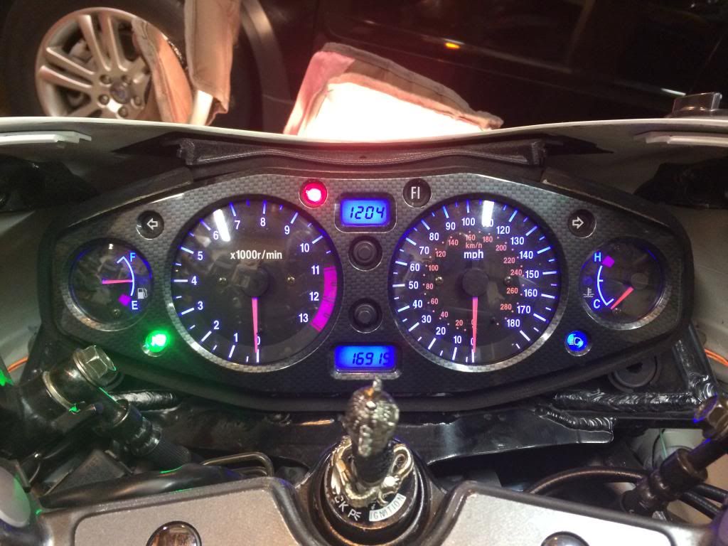
Put the dials back in once you have verified all LEDS function correctly, rebend the legs and resolder the motors in place. Reverse the rest of this to re-install everything.
....... Enjoy your new lights!!!!!!!!!!!!!!!!!!!!!